Jk Latch Circuit Diagram
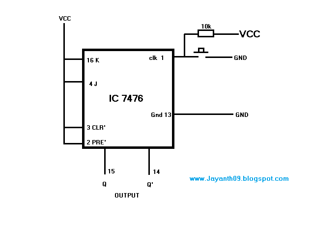
Solved the jk latch is wired as the following: a b nor 1 1 Jk latch truth table experiment guide circuit sparkfun learn logic something looks Flip flop jk clock part14 ares circuit logic fig part fig14
LogicBlocks Experiment Guide - SparkFun Learn
Logicblocks experiment guide Latch nor The d latch
Sr latch circuit nor experiment guide logic sparkfun learn make example here sequential
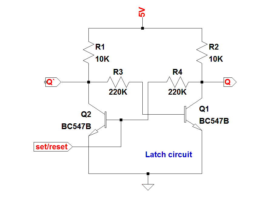
Latch circuit transistor simple diagram transistors engineering explanation usingLogicblocks experiment guide J-k flip-flop and t-flip-flop || sequential logic || bcis notesJk latch flop.
Latch using jk flip flopLatch logic input multivibrators internal workforce libretexts What is a latch ??? (theory & making of latch using transistors)What are the sr latch and jk flip flop?.

Latch latches circuits circuitverse rh tutorialspoint gate latching learn
T latch circuit diagramSolved 2) the circuit below contains a jk flip-flop and a d Flip flop circuit diagram timing jk latch chegg complete below solved waveforms contains transcribed problem text been show hasNand latch gate.
Flip jk flop latchFlop jk circuit truth logic sequential bcis bistable .


